
- USB PIC PROGRAMMER 16F1786 HOW TO
- USB PIC PROGRAMMER 16F1786 SERIAL
- USB PIC PROGRAMMER 16F1786 CODE
- USB PIC PROGRAMMER 16F1786 BLUETOOTH
I currently have 2 entries for this years Hackaday Prize. Hopefully I'll be able to return to the 16F1786 and won't need to deal with that. If I have to I will stick with the PIC16F877A, but if I do I'll at least need an external Op-Amp connected (to amplify the signal from the strip). Next step is attaching and sending text to a standard 16x2 LCD. It's taken me a few days of reading, trial, and error but I've finally gotten an LED to blink (pretty impressive right!).
USB PIC PROGRAMMER 16F1786 CODE
#pragma config CP = OFF // Flash Program Memory Code Protection bit (Code protection off) #pragma config WRT = OFF // Flash Program Memory Write Enable bits (Write protection off all program memory may be written to by EECON control)

#pragma config CPD = OFF // Data EEPROM Memory Code Protection bit (Data EEPROM code protection off)
USB PIC PROGRAMMER 16F1786 SERIAL
#pragma config LVP = OFF // Low-Voltage (Single-Supply) In-Circuit Serial Programming Enable bit (RB3 is digital I/O, HV on MCLR must be used for programming) #pragma config BOREN = ON // Brown-out Reset Enable bit (BOR enabled) #pragma config PWRTE = OFF // Power-up Timer Enable bit (PWRT disabled) #pragma config WDTE = OFF // Watchdog Timer Enable bit (WDT disabled) My other Configuration Bit settings were: #pragma config FOSC = XT // Oscillator Selection bits (XT oscillator) I ended up having to change the oscillator setting to: pullup resistor on MCLR/Vpp (pin 1) - around 5-10Kīefore building the project you need to be certain that the Configuration Bits are set correctly and added into the start of the code.100uF ceramic caps across pins 11/12 and 31/32.In addition to this, there are a few other points to consider: As I found out - that is wrong, PGD (ICSPDAT) is the Data pin (pin 40) and PGC (ICSPCLK) is the Clock pin (pin 39). Looking at the diagram, you may think, as I did, that pins 25 and 26 are the Clock and Data pins. The MCLR/Vpp pin is obviously pin 1 of the chip. Referring to the pin out for the PIC16F877A chip: That leaves the other 4 pins - actually 3 since pin 6 is not used here. VDD and VSS could easily have confused me but I knew from prior reading that VDD is + power and VSS is ground. Pin #1 is designated on the connected by a solid white arrow. I didn't really know if it still worked after de-soldering it from devices and I'm not really sure how I could test it but took my chances and used it anyway.Īfter everything was assembled I needed to connect the PICkit3 programmer. After going through crystals I scavenged from old electronics, I found a 4MHz ceramic (3 pin, no need for external capacitors) oscillator. Bread boarding the circuit was no problem from the schematic:Īs I put together the circuit on a solderless bread board I realized that I did not order any crystals for the timer oscillator (I'd spent so much time going over the datasheet for the PIC16F1786, from the glucometer reference design, that I never realized that the 877A has no internal oscillator).
USB PIC PROGRAMMER 16F1786 HOW TO
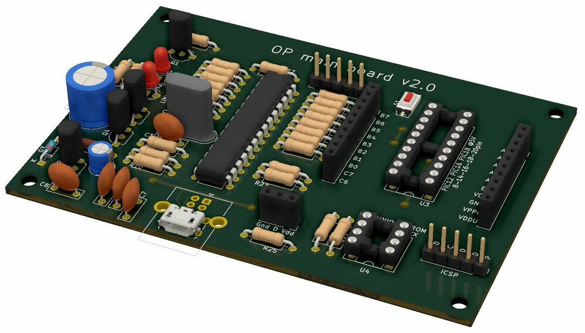
The first hurdle I needed to make it over was how to actually connect the PICkit3 to the micro-controller (in hindsight, if I had started with a Development Board this would not have been an issue). The tutorial I worked from was Blink LED with PIC16F877A. The first program I wanted to try was the most basic, a simple "Hello World" program that blinks an LED. Since I have some books that use them for learning to code in C for Back when I ordered my last LCD screen (which is actually the wrong one for the reference design from Microchip) I also ordered a few PIC16F877A chips (PICkit3 clone) actually works and that I can actually upload programs (I know compiling programs works but I haven't actually uploaded anything). First order of business was to ensure my programmer I decided to take a step back and return to some real basic level stuff for programming and using PIC Microcontroller's. I posted the basic details of this on Hackaday earlier, thought I's post the some of the nitty gritty details here. Looks like the top 5 finalists (1st through 5th place) will be announced at the Hackaday Superconference Nov.
USB PIC PROGRAMMER 16F1786 BLUETOOTH


 0 kommentar(er)
